
At a client's meeting, we discussed how the bottom stirring elements of a typical LD-BS converter should be arranged with respect to the oxygen jets and other factors.
Most of the time, a drawing is made for one specific configuration to answer this question. This is followed by a lot of other versions and iterations of this drawing where each parameter (e.g., lance height, nozzle spreading angle) is modified. This can get quite time-consuming.
Bothered with this method, we started to build a model to visualize the oxygen-jets and the position of the bottom stirring elements in a BOF.
Here is the result:
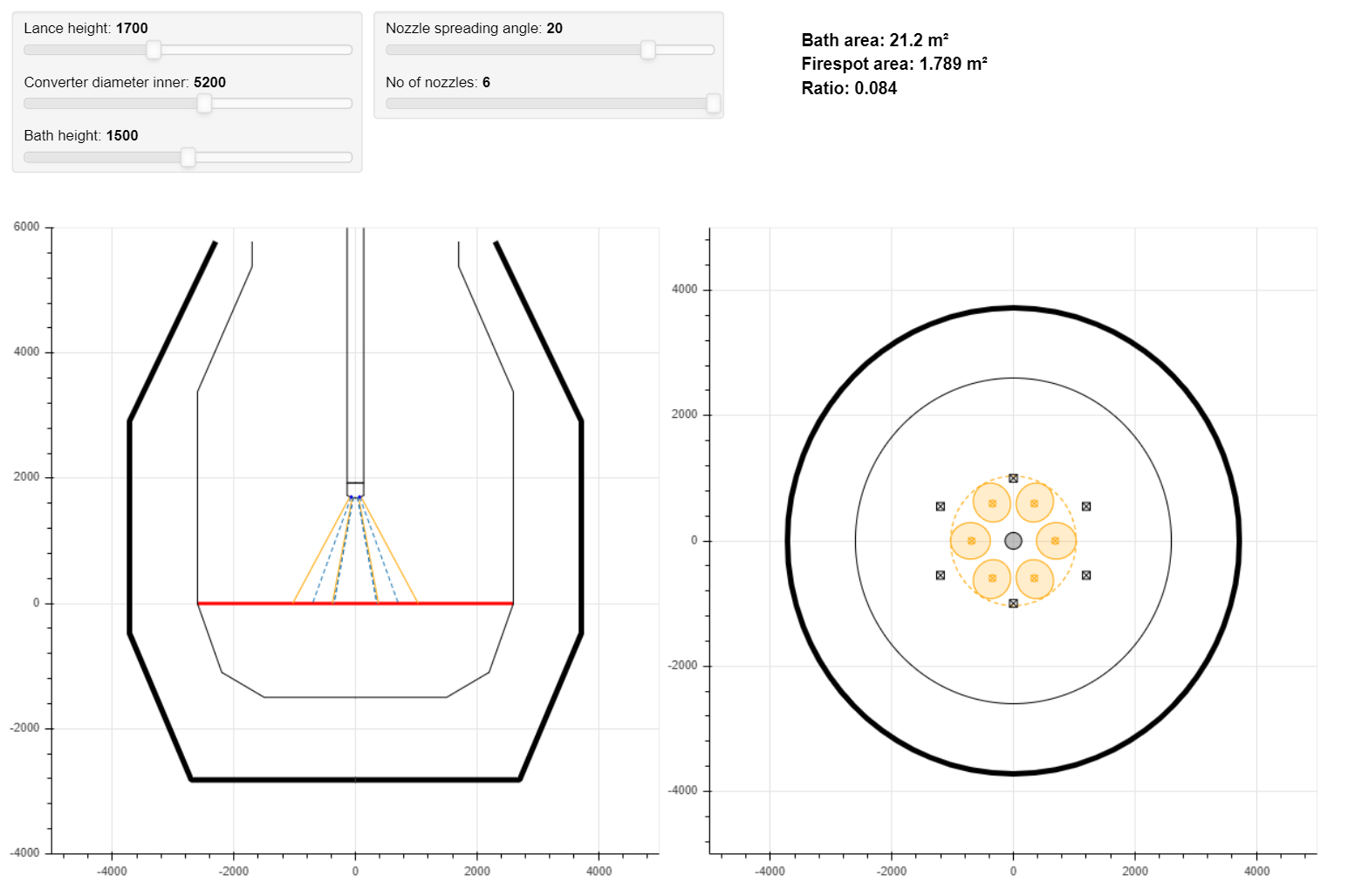
The visualization is interactive, so you can adapt the model completely to your own converter configuration (incl. inner/outer vessel shape). The full list of parameters which you can modify is:
- Converter diameter inner
- Bath height
- Lance height
- Nozzle spreading angle
- No. of nozzles
- Nozzle offset lance center
- Nozzle diameter exit
- Jet spreading angle
- Lance outer diameter
- Position of stirring elements
- Inner lining geometry
- Outer shell geometry
(There is a description of all the parameters and how to edit them in the app.)
Furthermore, we calculate some KPIs like:
- Bath area
- Fire spot area
- Ratio (fire sport and bath area)
Those can be used to see the difference between certain lance/tip/converter configurations. Clearly, some important KPIs like jet impact profile (velocity, pressure above bath) would be helpful to better describe the dynamics. However, these require additional calculations (De Laval nozzle, jet velocity decay/profile) which would be too much for the current phase (see development road-map).
Calculation Approach and Limitations
The calculation is based on geometrical factors only. The most critical variable is clearly the jet spreading angle. This single parameter is influenced by a lot of factors (jet/environment temperature, jet velocity, nozzle arrangement, etc.) and would need a proper CFD simulation to be precisely determined.
Moreover, it is known that the jets don't develop in a straight line [1]. They are influenced by the neighboring jets and therefore tend to bend inwards, towards each other. However, this jet coalescence is (currently) not taken into account.
Nevertheless, the model does a good job in providing a fast way to get an overview of the current situation. Typical values for the jet spreading angle range between 7-13°.
Development Road-map
We have some ideas we want to integrate over time. Our next development targets are:
Import and export of data(UPDATE: implemented in v0.3)- De Laval nozzle design and calculation
- Jet coalescence model
- Estimated jet velocity of center line trajectory, radial velocity and impact velocity profile above bath.
Want to use it?
The application is free for everybody to use. Just write me an email to
p.uhl-haedicke@smartsteelmaking.com and I will send you an individual link to the application.
Feedback or suggestions?
We welcome any feedback, suggestions, recommendations for papers, feature requests, etc.! Just write us an email or comment below at the end of the article.
For more information on what we are actually doing, visit: www.smartsteelmaking.com
Thanks for reading. Till soon!
Paul
References:
[1] Li, Mingming & Li, Qiang & Li, L. & He, Yibo & Zou, Z.. (2014). Effect of operation parameters on supersonic jet behaviour of BOF six-nozzle oxygen lance. Ironmaking & Steelmaking. 41. 699-709. 10.1179/1743281213Y.0000000154.